Difference between revisions of "S0 serial reader"
From PhotoVoltaic Logger new generation
m (→USB to TTL Serial Cable) |
m (→USB to TTL Serial Cable) |
||
| Line 38: | Line 38: | ||
=== USB to TTL Serial Cable === | === USB to TTL Serial Cable === | ||
| − | |||
| − | |||
I found also a bit cheaper possibility, a USB to TTL Adapter with 6 pins. | I found also a bit cheaper possibility, a USB to TTL Adapter with 6 pins. | ||
This cable is originally used for Arduino compatible boards but it works perfect also for S0 signals. | This cable is originally used for Arduino compatible boards but it works perfect also for S0 signals. | ||
| + | |||
| + | [[File:FTDI-FT232-USBtoTTL.jpg|320px]] | ||
'''''Please note:''''' | '''''Please note:''''' | ||
Revision as of 13:06, 28 February 2014
Contents
Abstract
This is a part of the PVLng-scripts repository.
Scripts located in S0/
To read S0 impulses from e.g. energy meters, a program and a script to store this into PVLng is included.
Hardware requirements
Energy meter
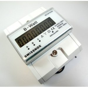
You need a energy meter with S0 interface, best for 3 phases.
Serial port adapter
If your computer not more have a serial port (like mine), you need a USB serial adapter.
The best choice is an adapter with a FTDI / FT232RL chip set.
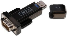
Digitus DA-70156 USB to Serial Adapter, USB 2.0
During prototyping a gender changer (female/female) is recommended.
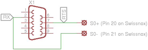
Connect your S0 port like this to your serial interface:
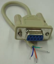
Or you recycle an old serial mouse cable...
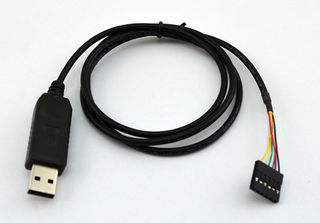
USB to TTL Serial Cable
I found also a bit cheaper possibility, a USB to TTL Adapter with 6 pins.
This cable is originally used for Arduino compatible boards but it works perfect also for S0 signals.
Please note:
- You need a cable with 6 pins, not only 4 pins, although we need only 2 of them!
| Wire | Signal |
|---|---|
| Red | 5V |
| Black | GND |
| White | RXD |
| Green | TXD |
| Yellow | RTS |
| Blue | CTS |
You can find them on eBay, shipping from China to Germany took abt. 3 weeks.
Test
adapted from Volkszähler wiki
You should test your setup, to make sure, the signals will be correct detected.
A simple test can be done with stty.
Configure your device (50 Baud, return direct every character):
$ stty time 1 min 1 -icanon < /dev/ttyUSB0
Simply read each character and create a timestamp:
$ strace -ttt -e read cat < /dev/ttyUSB0 > /dev/null
With a bit more code you can better check the results:
$ (strace -ttt -e read cat < /dev/ttyUSB0 > /dev/null) 2>&1 | \
  awk 'NR==1{t0=$1; next}{t=$1; print 3600e3 /(t-t1)/2000, t-t0, t-t1, $0; t1=t}'
Adjust the device and the 2000 to the impulse rate of your watt meter!
| Result column | Description |
|---|---|
| 1 | Power in watt |
| 2 | Current time in seconds |
| 3 | Time difference since last impulse |
| 4 | Original trace output with timestamp |
Channel definition
Please put the device where your energy meter is connected to into the channel attribute like this:
You should also define a fixed name for your device.
Mode of operation
An energy meter with S0 interface sends depending of the actual power usage an amount of impulses per kilo watt hour.
A common frequency is 1000 or 2000 per kilo watt hour, or 800 as for our energy meter.
The S0 binary listen the device and detects the time between these impulses. It converts them to power usage in watt.
Installation
$ cd S0/bin
$ ./compile
Configuration
Please refer to S0.conf.dist to configure your environment regarding interfaces and channels.
$ cp S0.conf.dist S0.conf
Test
To test your configuration, run
$ ./S0.sh -tv S0.conf
Run with cron
Edit your crontab with
$ crontab -e
and add the following lines
# run S0 reader each 2 minutes
*/2 * * * * /path/to/PVLng-sctipts/S0/S0.sh S0.conf
