Difference between revisions of "1-Wire Hub"
From PhotoVoltaic Logger new generation
m |
m |
||
| Line 11: | Line 11: | ||
If you have long 1-Wire network runs and are having problems with glitches you should add a Schottky diode to the end of your network. Typically a 1N5817 diode reverse biased across sensors will achieve this. Solder the side with the stripe to data output (DQ pin 2) and the other side to ground (GND pin 1) of the DS18S20. | If you have long 1-Wire network runs and are having problems with glitches you should add a Schottky diode to the end of your network. Typically a 1N5817 diode reverse biased across sensors will achieve this. Solder the side with the stripe to data output (DQ pin 2) and the other side to ground (GND pin 1) of the DS18S20. | ||
| − | <references> | + | <references /> |
== Draft == | == Draft == | ||
Revision as of 21:58, 22 March 2014
I monitor here 3 1-Wire DS18B20[1] based temperature sensors.
As I looked at commercial solutions and their prices, I decided to construct my own 1-Wire hub.
The DS18B20 temperature sensor can be powered by an external supply on the VDD pin, or it can operate in "parasite power" mode, which allows the DS18B20 to function without a local external supply[2].
- In normal mode, each sensor is connected between a power line (VDD pin 3) and ground (GND pin 1), and the data output (DQ pin 2) connects to a third, data, line. The data output is a 3-state or open-drain port (DQ pin 2) and a 4.7 kΩ pull-up resistor to the power line is required.
- Parasite power mode requires both DS18B20 GND (pin 1) and VDD (pin 3) to be connected to ground. The DQ pin (pin 2 - the middle pin) is the data/parasite power line. The data line requires also a pull-up resistor of 4.7 kΩ connected to +5 V.
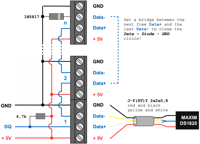
If you have long 1-Wire network runs and are having problems with glitches you should add a Schottky diode to the end of your network. Typically a 1N5817 diode reverse biased across sensors will achieve this. Solder the side with the stripe to data output (DQ pin 2) and the other side to ground (GND pin 1) of the DS18S20.
Draft
So put all together to get an imagination.
Please note:
- Mind the diode and the resistor!
The trick to build a linear topology is, that each sensor is connected with 4 wires. The DQ data pin 2 is connected with 2 wires of the cable, to build a single long line.
Build
- As small as possible
- Simple to build > breadboard platine
- Stable > Normal mode
- Linear topology (according to this guidelines) > more stable than star topologies
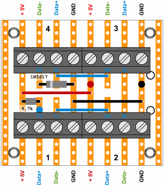
Put it all together and minimize.
(View from top, printed circuits and soldering on the bottom)
The cyan, red and black thick dots are the soldering points for the upstream Data, +5V and GND wires.
Use a bit thicker telephone cable J-Y(St)Y 2x2x0.8mm for lower loop impedance.
| Parts list | Source of supply | Price |
|---|---|---|
| Lötbare Schraubklemme, RM 5.0mm | Conrad | € 0.33 |
| Lötstreifenrasterplatte | Conrad | € 2.94 |
| Schottky-Diode 1N5817RLG | Conrad | € 0.25 |
| Kohleschicht-Widerstand 4,7 kΩ | Conrad | € 0.10 |
| Universal-Gehäuse 120x65x40 BOXE | Conrad | € 3.98 |
| Telefoninnenkabel J-Y(ST)Y 2x2x0.8mm | Conrad, eBay | € 1.19/m |


